Last edited: Jun 30, 2018
NCIDdisplay Matrix Assembly
Bill of Materials
If you do not have access to tools to cut/mill plexiglass, an alternative is to score/break the plexiglass to size with a scoring tool. Additional details about this method are available on wikihow. If you plan to use the score/break method, it is recommended that you use 0.118" thick plexiglass.
Need a Wi-Fi connected NCIDdisplay? While preliminary testing of an Arduino Yun has been successfully performed, there are latency issues with the Yun Bridge. As a result, it is recommended that you use an ethernet bridge for Wi-Fi connectivity. A cost-effective and very stable alternative is the TP-LINK TL-WR702N Wireless N150 Travel Router that can easily be setup as an ethernet bridge.
Program Arduino Ethernet
- Download and install the Arduino IDE if you do not already have it installed. Any version >=1.0 should work.
- Download nciddisplay-0.6-src.tar.gz from ncid.sourceforge.net, extract the file and copy the files within the extracted directory (nciddisplay) into a directory named NCIDdisplayLED in your Arduino sketch folder.
- Program the Arduino Ethernet:
- Connect USB Serial Adapter to your computer’s USB port and the FTDI/Serial port on the Arduino Ethernet
- Start Arduino IDE
- Set tools/board to: Arduino Ethernet
- Set serial port to location of board
- Open the NCIDdisplayLED.ino sketch. Modify the following to match your network:
- MAC address (ensure that it is unique for your network; default is likely okay unless you have multiple NCIDdisplays on your network)
- IP address of the ethernet controller used by NCIDdisplay(ensure that it is unique for your network)
- IP address of NCID server
- Gateway IP address (typically the ip address of your router)
- Subnet mask (unlikely that you will need to change this for a home network)
- Port used by NCID server (only change from the default of 3333 if you have changed your NCID server’s port away from the default)
In other words, in NCIDdisplayLED.ino, review and modify the following lines as appropriate for your setup:
      /*
       * the media access control (MAC) address for the shield
       * change if another shield is has this MAC address
       */
      byte mac[] = { 0xDE, 0xAD, 0xBE, 0xEF, 0xFE, 0xEE };

      // Change for your network
      byte ncidServer[] = { 10, 0, 0, 7 };  // IP address of your NCID server
      byte ip[]         = { 10, 0, 0, 79 };   // the IP address for the NCIDdisplay
      byte gateway[]    = { 10, 0, 0, 1 };   // gateway address for your network
      byte subnet[]     = { 255, 255, 255, 0 }; // the subnet mask
- Click the Upload button (right pointing arrow just below menu bar) to compile and upload the sketch to the Arduino.
NOTE: It is strongly recommended to NOT program the Arduino while it is plugged into the LED matrix panel assembly.
Hardware Assembly
Cut 36" x 1/2" x 1/16" aluminum into 2 pieces 18" x 1/2" x 1/16“. Drill 3/16” holes to align with the holes in LED Matrix panels. Use DrillingTemplate.pdf (see source code ‘assembly’ directory) to assist with drilling the holes.
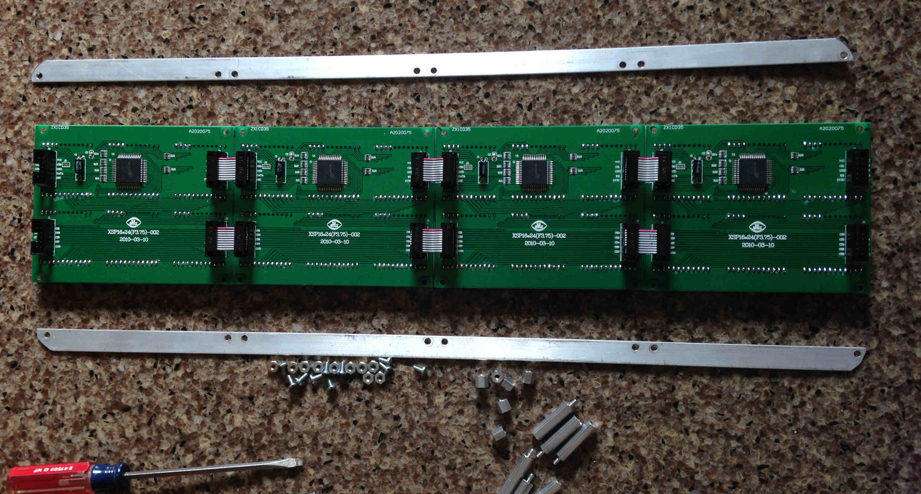
Mount the LED Matrix Panels on the aluminum bars from Step 1 using the 10x 4-40 x 1/4" screws, 10x 4-40 nuts and the hex binding posts. The hex binding posts go in the 4 holes on the outside and 2 holes near the middle holes.
- Cut the plexiglass to a size to suit your desired look; as a suggestion, make the plexiglass 1/4" to 1/2" larger than the overall LED matrix panel. Drill 3/16" holes to allow screws to connect the plexiglass to the hex binding posts. Use DrillingTemplate.pdf (see source code ‘assembly’ directory) to assist with drilling the holes. 6 holes in each plexiglass panel provide good stability of the completed assembly.
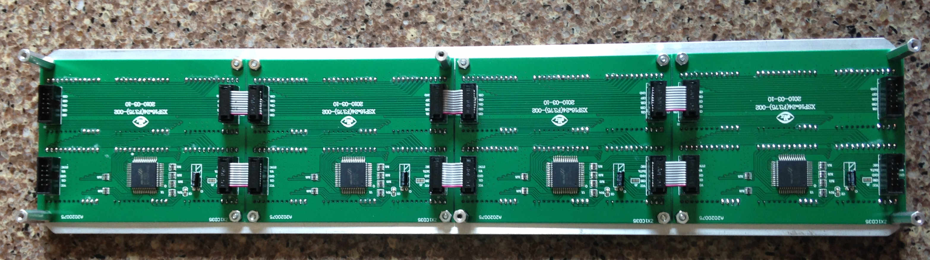
- Connect the LED Matrix Panels together with the 6x 10-pin Socket/Socket IDC cables as shown in the picture for Step 2.
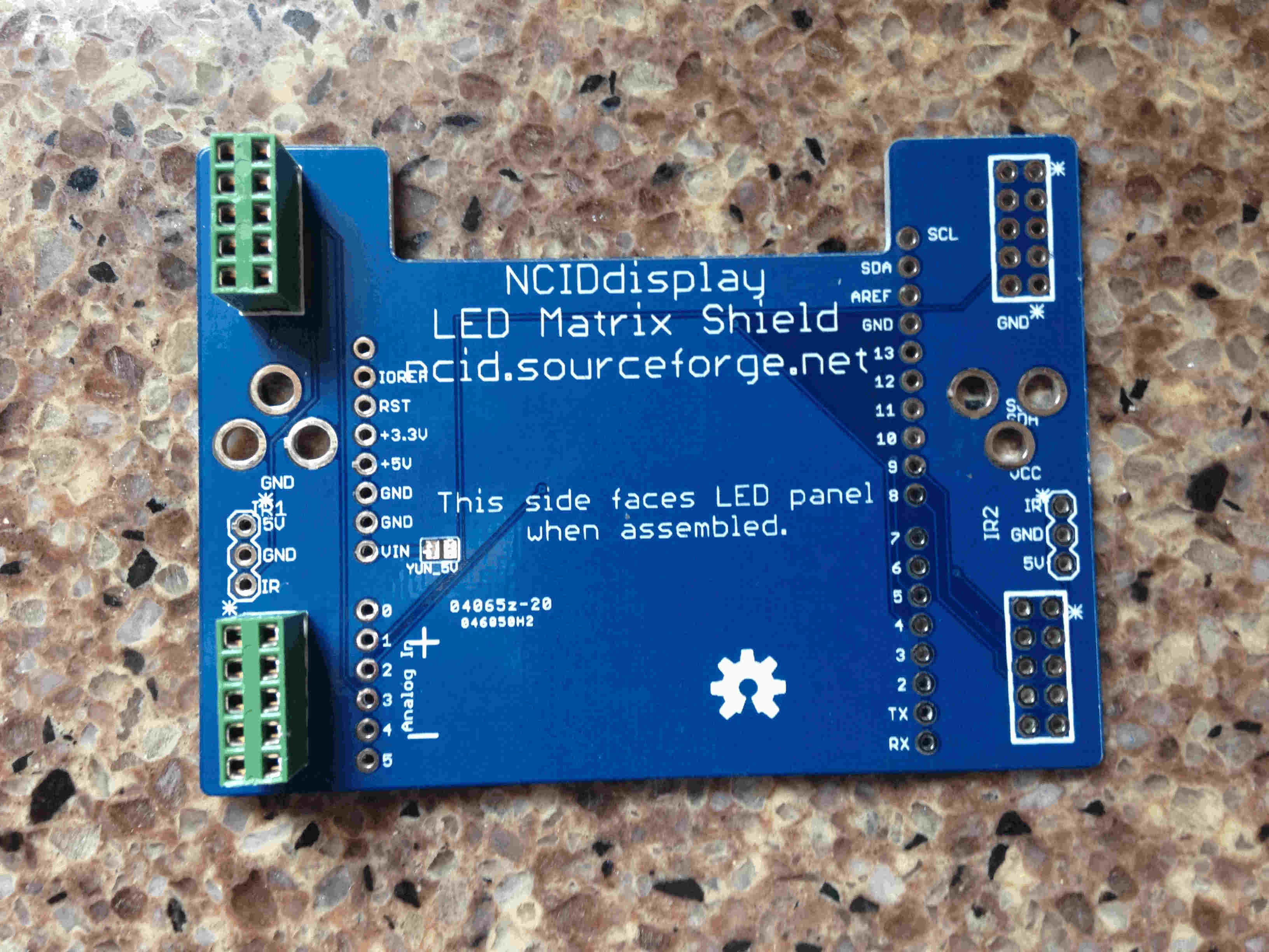
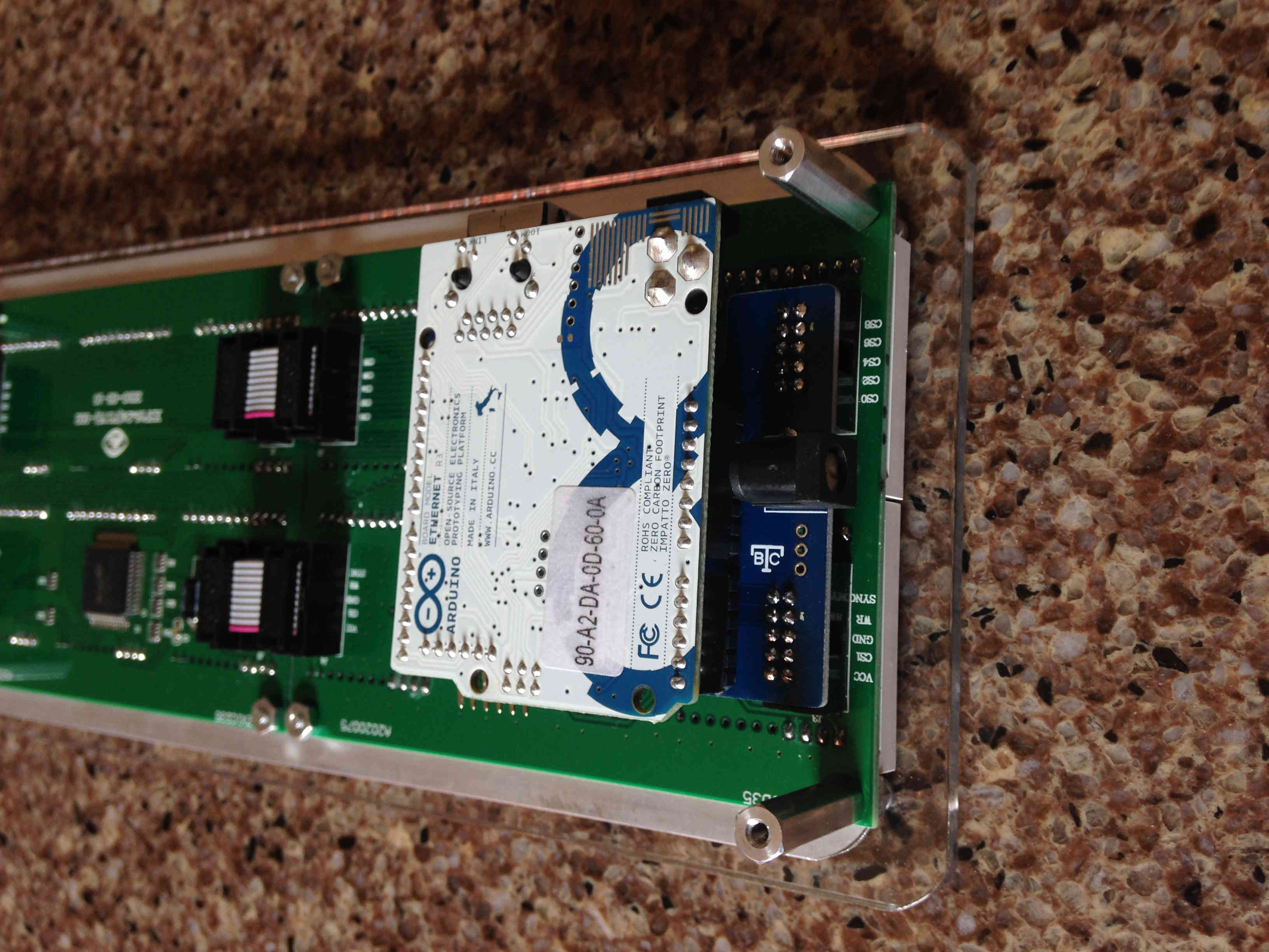
- Insert the 2x5 0.1" female headers into the appropriate holes on the NCIDdisplay PCB. It is possible to rotate the NCIDdisplay PCB so that the Ethernet port is either pointing up or down depending on your needs. Solder all connections on the 2x5 headers. The photo below shows the orientation that will result in the Ethernet jack facing the top of the final assembly. The specified 2x5 headers have retentive pins to make it easier to flip the board over to solder the pins. Solder the pins.
- If desired, you can solder 2x5 female headers in all four locations to allow either orientation.
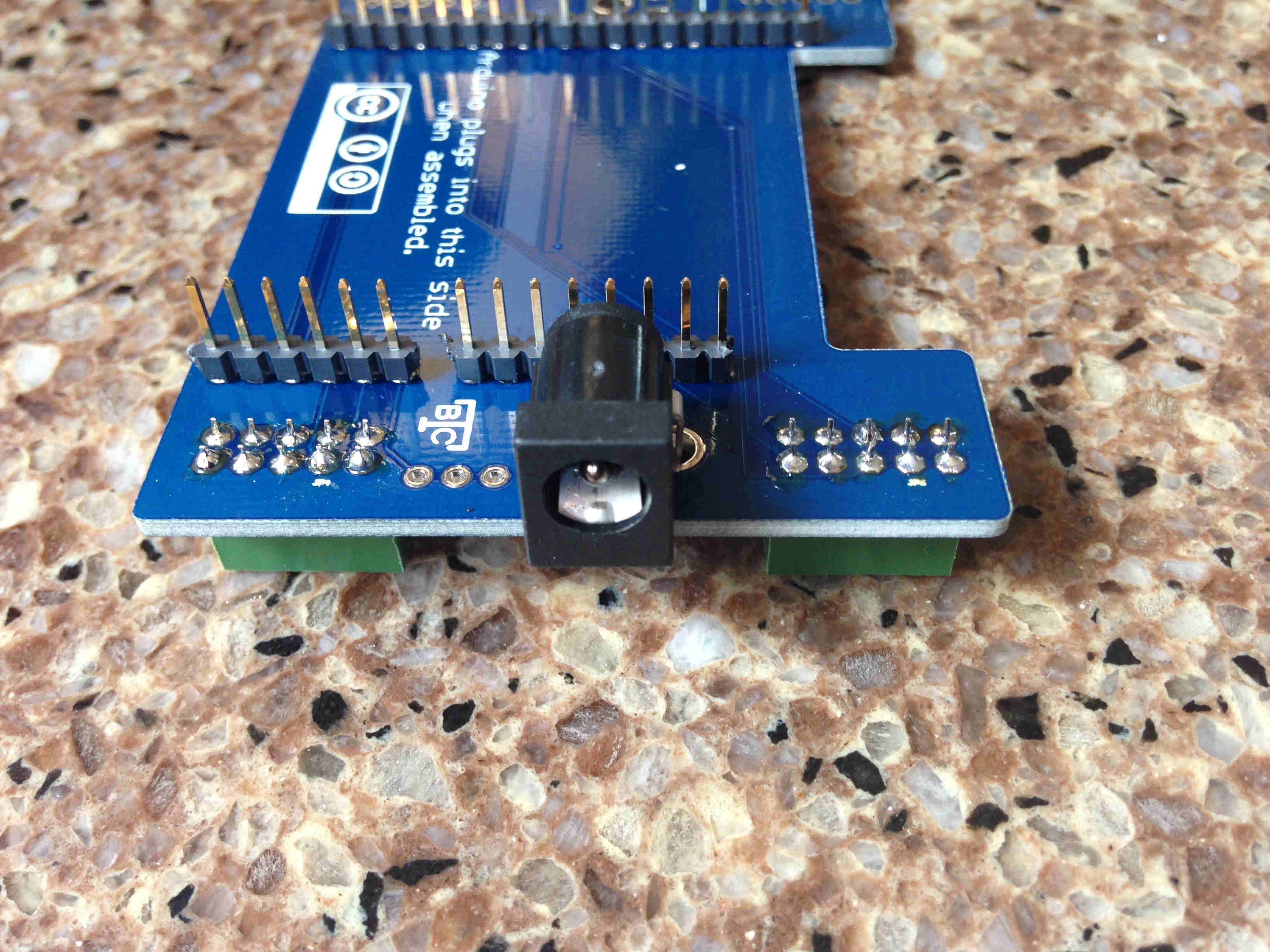
Align the NCIDdisplay PCB with the Arduino so that the 0.1" breakaway headers are inserted through the appropriate holes. Solder the pins.

Remove the Arduino from the NCIDdisplay PCB. Solder the 2.1mm x 5.5mm DC barrel jack in place.
- Program the Arduino with the NCIDdisplayLED.ino sketch if you have not done so already (see above section on programming the Arduino).
Connect the Arduino to the NCIDdisplay PCB. Press this assembly into the LED Matrix Panel.
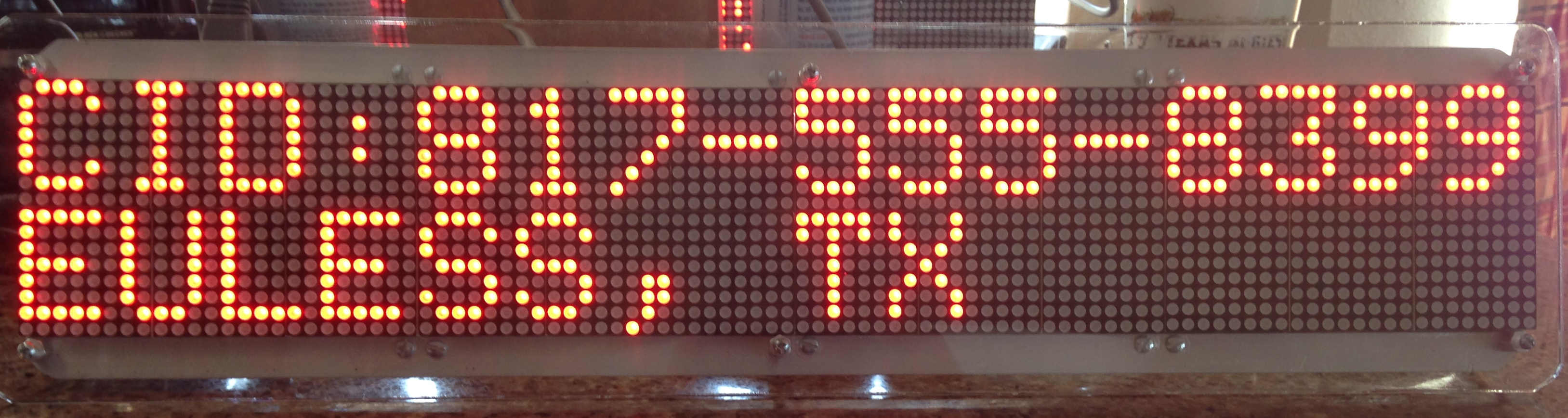
- DO NOT USE THE POWER CONNECTOR ON THE ARDUINO BOARD. Provide regulated 5V, 2A of power to the system through the power connector on the NCIDdisplay PCB. If you have done everything correctly, the NCIDdisplay will show that it is connected to your NCID server and then display the most recent call from the NCID call log.
- Once everything is working, attach the front and back plexiglass panels with 4-40 screws.
Finished! Below are some examples of NCIDdisplay in action.


Version
0.6
License
The hardware design (schematics, pcb and assembly) is licensed under a Creative Commons Attribution-ShareAlike 4.0 International License. Click the icon below for more information on this license.

The software/firmware license is GPL 2 or later; full details are in the source code.